 |
|
SMD Soldering Guide by Infidigm |
|
|
Purpose
The purpose of this guide is to introduce SMD (Surface Mount Device) hand soldering. The
guide is organized into different methods. Each method is used specifically for a group of SMD components. A
simplified list is included with each method to identify which types of SMD components are for the appropriate
method.
Please visit Introduction to soldering in general, if you have never soldered before.
SMD Hand Soldering Methods
- Method 1 - Pin by pin Used for : two pin components (0805 caps & res), pitches
>= 0.0315" in Small Outline Package, (T)QFP and SOT (Mini 3P).
- Method 2 - Flood and suck Used for : pitches <= 0.0315" in Small Outline
Package and (T)QFP
- Method 3 - Solder paste Used for BGA, MLF / MLA packages; where the pins are
underneath the part and inaccessible.
- Desoldering SMD Special methods for desoldering without the need for special
soldering iron tips.
Used for :
Diodes, Capacitors and Resistors in sizes like 0603, 0805, 1206, 1210, 1812, 1825, 3216, 3528, 6032, and 7343.
Small Outline Packages and QFP with pitches >= 0.0315". Like SO.050" and SO.80mm (0.0315")
SOT packages like SOT223, SOT23, SOT143, SOT89, Mini-5P, and Mini-6P.
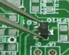
0805 Capacitor example :
|
|
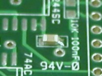
 Step 1 Place a small amount of
solder on one of the two pads. Aprox. 0.5mm in height. Step 1 Place a small amount of
solder on one of the two pads. Aprox. 0.5mm in height.
|
|
|
|
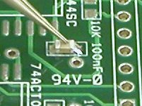
 Step 2 Grab the 805 part with very
fine tweezers. Bring the part overtop of the pads, slight to one side so that the part can sit flat against
the PCB. Heat the pad already with solder and slide the part onto the pad so that it is centered between the
pads. Remove heat. Step 2 Grab the 805 part with very
fine tweezers. Bring the part overtop of the pads, slight to one side so that the part can sit flat against
the PCB. Heat the pad already with solder and slide the part onto the pad so that it is centered between the
pads. Remove heat.
|
|
|
|
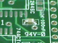
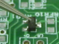
 Step 3 Put a small force down on the
part and re-heat the one pad to guarantee that the parts is flat against the PCB. Step 3 Put a small force down on the
part and re-heat the one pad to guarantee that the parts is flat against the PCB.
|
|
|
|
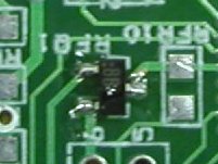
 Step 4 Solder the other side of the
part. Step 4 Solder the other side of the
part.
|
|
The solderings should not look like "round ball" on either side of the parts. If this is the cast, there is too
much solder being appied to the joint. A properly soldered joint should have a curved line from the end of the pad
to the top of the part as shown in the pictures.
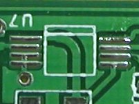
Small Outline Package - SO.050 example :
|
|
 Step 1 Place a small amount of
solder on one of the conner pads. Aprox. 0.5mm in height. Step 1 Place a small amount of
solder on one of the conner pads. Aprox. 0.5mm in height.
|
|
|
|
 Step 2 Grab the 14 pin SOP part with
very fine tweezers. Bring the part overtop of the pads, sit the part on top of the pads. Heat the pad with
solder and adjust the part so that it lines up with the pads. Besure the part is flat and aligned, then
remove the heat. Step 2 Grab the 14 pin SOP part with
very fine tweezers. Bring the part overtop of the pads, sit the part on top of the pads. Heat the pad with
solder and adjust the part so that it lines up with the pads. Besure the part is flat and aligned, then
remove the heat.
|
|
|
|
 Step 3 Now solder the rest of the
pins, one-at-a-time. Use a chise tpye tip (1/32" wide). Contact the pin and pad at the same time with the
conrner of the tip. Do not use the end of the tip or solder will flow from pin to pin. Start with the pin at
the adjacent corner to the pin already started. Step 3 Now solder the rest of the
pins, one-at-a-time. Use a chise tpye tip (1/32" wide). Contact the pin and pad at the same time with the
conrner of the tip. Do not use the end of the tip or solder will flow from pin to pin. Start with the pin at
the adjacent corner to the pin already started.
|
|
SOT23 example :
|
|
 Step 1 Place a small amount of
solder on one of the three pads. Aprox. 0.5mm in height. Step 1 Place a small amount of
solder on one of the three pads. Aprox. 0.5mm in height.
|
|
|
|
 Step 2 Grab the SOT23 part with very
fine tweezers. Bring the part overtop of the pads, slight to one side so that the part can sit flat against
the PCB. Heat the pad already with solder and slide the part onto the pad so that it is centered between the
three pads. Remove heat. Step 2 Grab the SOT23 part with very
fine tweezers. Bring the part overtop of the pads, slight to one side so that the part can sit flat against
the PCB. Heat the pad already with solder and slide the part onto the pad so that it is centered between the
three pads. Remove heat.
|
|
|
|
 Step 3 Put a small force down on the
part and re-heat the one pad to guarantee that the parts is flat against the PCB. Step 3 Put a small force down on the
part and re-heat the one pad to guarantee that the parts is flat against the PCB.
|
|
|
|
 Step 4 Now solder the other two
pins, one-at-a-time. Use a chise tpye tip (1/32" wide). Contact the pin and pad at the same time with the
conrner of the tip. Do not use the end of the tip or solder will flow from pin to pin. Step 4 Now solder the other two
pins, one-at-a-time. Use a chise tpye tip (1/32" wide). Contact the pin and pad at the same time with the
conrner of the tip. Do not use the end of the tip or solder will flow from pin to pin.
|
|
Used for :
Small Outline packages and (T)QFP with pitches <= 0.0315". Like SO.025", SO.80mm (0.0315"), SO.65mm (0.0256"),
SO.50mm, SO.40mm, and SO.30mm.
Small Outline Package - SO.65mm example :
|
|
 Step 1 Place a small amount of
solder on one of the conner pads. Aprox. 0.5mm in height. Step 1 Place a small amount of
solder on one of the conner pads. Aprox. 0.5mm in height.
|
|
|
|
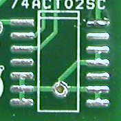
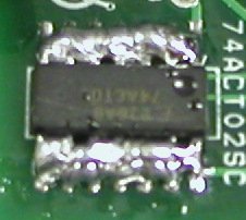
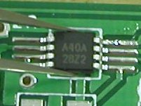 Step 2 Grab the 8 pin SOP part with
very fine tweezers. Bring the part overtop of the pads, sit the part on top of the pads. Heat the pad with
solder and adjust the part so that it lines up with the pads. Besure the part is flat and aligned, then
remove the heat. Step 2 Grab the 8 pin SOP part with
very fine tweezers. Bring the part overtop of the pads, sit the part on top of the pads. Heat the pad with
solder and adjust the part so that it lines up with the pads. Besure the part is flat and aligned, then
remove the heat.
|
|
|
|
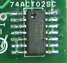
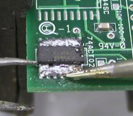
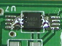 Step 3 Now flood the opposite row of
pins with solder so that there is one continuous flow across the pins as shown. Continue by flooding the
other row of pins. Try to keep the solder across the pins as even as possible. Step 3 Now flood the opposite row of
pins with solder so that there is one continuous flow across the pins as shown. Continue by flooding the
other row of pins. Try to keep the solder across the pins as even as possible.
|
|
|
|
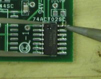
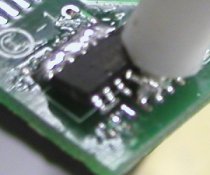
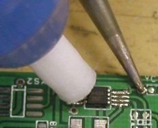 Step 4 Using the iron, (or a heated
sucker) heat one end of the pins until the solder is melted 2-3 pins in length from the end. Quickly remove
the iron and using a solder sucker, suck the excess solder from between the pins. Heat the solder on the next
2-3 pins and do the same until the other end is reached. Do the same on the other side of the chip. Finally
inspect the pins to check if any solder is left between them. If there is, re-apply solder between the pins
and re-suck. This method works because sucking only removes the solder between the pins and not the solder
between the pad and pin. Step 4 Using the iron, (or a heated
sucker) heat one end of the pins until the solder is melted 2-3 pins in length from the end. Quickly remove
the iron and using a solder sucker, suck the excess solder from between the pins. Heat the solder on the next
2-3 pins and do the same until the other end is reached. Do the same on the other side of the chip. Finally
inspect the pins to check if any solder is left between them. If there is, re-apply solder between the pins
and re-suck. This method works because sucking only removes the solder between the pins and not the solder
between the pad and pin.
|
|
(Thin) Quad Flat Package - SO.80mm example :
|
|
 Step 1 Place a small amount of
solder on one of the conner pads. Aprox. 0.5mm in height. Step 1 Place a small amount of
solder on one of the conner pads. Aprox. 0.5mm in height.
|
|
|
|
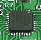
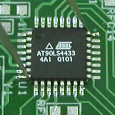 Step 2 Grab the 32 pin TQFP part
with very fine tweezers. Bring the part overtop of the pads, sit the part on top of the pads. Heat the pad
with solder and adjust the part so that it lines up with the pads. Besure the part is flat and aligned on all
four sides, then remove the heat. Step 2 Grab the 32 pin TQFP part
with very fine tweezers. Bring the part overtop of the pads, sit the part on top of the pads. Heat the pad
with solder and adjust the part so that it lines up with the pads. Besure the part is flat and aligned on all
four sides, then remove the heat.
|
|
|
|
 Step 3 Now flood the opposite row of
pins with solder so that there is one continuous flow across the pins as shown. Continue by flooding the
other three rows of pins. Try to keep the solder across the pins as even as possible. Step 3 Now flood the opposite row of
pins with solder so that there is one continuous flow across the pins as shown. Continue by flooding the
other three rows of pins. Try to keep the solder across the pins as even as possible.
|
|
|
|
 Step 4 Using the iron, (or a heated
sucker) heat an end of a row until the solder is melted 2-3 pins in length from the end. Quickly remove the
iron and using a solder sucker, suck the excess solder from between the pins. Heat the solder on the next 2-3
pins and do the same until the other end is reached. Do the same on the other three sides of the chip.
Finally inspect the pins to check if any solder is left between them. If there is, re-apply solder between
the pins and re-suck. This method works because sucking only removes the solder between the pins and not the
solder between the pad and pin. Step 4 Using the iron, (or a heated
sucker) heat an end of a row until the solder is melted 2-3 pins in length from the end. Quickly remove the
iron and using a solder sucker, suck the excess solder from between the pins. Heat the solder on the next 2-3
pins and do the same until the other end is reached. Do the same on the other three sides of the chip.
Finally inspect the pins to check if any solder is left between them. If there is, re-apply solder between
the pins and re-suck. This method works because sucking only removes the solder between the pins and not the
solder between the pad and pin.
|
|
Used for :
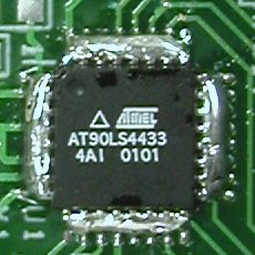
Used for BGA, MLF / MLA packages; where the pins are underneath the part and inaccessible.
Example :
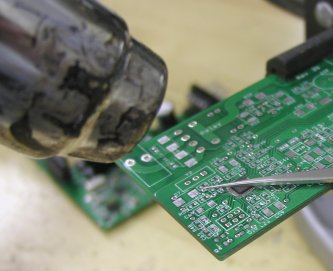
To use this method you will need a head gun or a PCB oven. The following instructions are for a heat gun only.
Mount the circuit board in a vise that will not burn when heated. It is recommended that the BGA, MLF / MLA parts
be soldered to the PCB first in order not to disturb the soldering of the other regular components. If this is not
possible then tin foil can be used to shield the regular components.
|
|
 Step 1 Set the part on the board and
line it up as it would be soldered. Take note and or mark the PCB so that you will be able to correctly place
the part when heating. Step 1 Set the part on the board and
line it up as it would be soldered. Take note and or mark the PCB so that you will be able to correctly place
the part when heating.
|
|
|
|
 Step 2 Spread a thin layer of solder
paste across the PCB on the pad area for the BGA, MLF / MLA part. The thickness of the solder paste should be
thin enough so that the PCB and pads should be semi-visible. The amount is learned by trail and error and
experience. Step 2 Spread a thin layer of solder
paste across the PCB on the pad area for the BGA, MLF / MLA part. The thickness of the solder paste should be
thin enough so that the PCB and pads should be semi-visible. The amount is learned by trail and error and
experience.
|
|
|
|
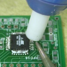
 Step 3 Place the BGA, MLF / MLA part
on the PCB and align. Use needle-nose pliers to hold the part in place while heating. Make sure the pliers
are not bare metal or they will get too hot to handle when heating. Using the heat gun, apply heat to the
part by holding the heat gun 8cm ( 3") away from the board. Step 3 Place the BGA, MLF / MLA part
on the PCB and align. Use needle-nose pliers to hold the part in place while heating. Make sure the pliers
are not bare metal or they will get too hot to handle when heating. Using the heat gun, apply heat to the
part by holding the heat gun 8cm ( 3") away from the board.
|
|
|
|
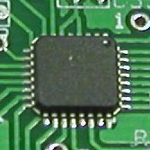
 Step 4 Keep heating until the solder
paste has melted into solder all the way around the part. (Should take 20 - 40 seconds) Be sure that the part
is aligned and remove the heat. Blow on the part to harden the solder. Inspect around the edges of the part
for solder bridges from pad to pad. If there are bridges you will need to reheat the part, remove it, suck
the solder from the pads and the part, and repeat the procedure with less solder paste. Step 4 Keep heating until the solder
paste has melted into solder all the way around the part. (Should take 20 - 40 seconds) Be sure that the part
is aligned and remove the heat. Blow on the part to harden the solder. Inspect around the edges of the part
for solder bridges from pad to pad. If there are bridges you will need to reheat the part, remove it, suck
the solder from the pads and the part, and repeat the procedure with less solder paste.
|
|
De-soldering SMD components without special soldering iron tips involves creativity. In most cases the SMD
component is destroyed. Try to find the proper tip / tool to de-solder before trying the following examples.
0805 Capacitor / Resistor de-soldering :
|
|
Two pin SMD component, such as a 0805 chip capacitor or resistor, is the easiest to de-solder with a
regular soldering iron tip. Simply heat one side until the solder is melted, then quickly move to the other
side until the solder is melted. Keep alternating between sides. This will build up heat on each side and the
part will slide off the pads in 5 - 10 seconds.
|
|
Small Outline Package - SO.050 example :
|
|
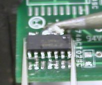
 Step 1 Flood the each row of pins
with solder so that there is one continuous flow across the pins as shown. Try to keep the solder across the
pins as even as possible. Get a small screwdriver ready to insert under the part. Step 1 Flood the each row of pins
with solder so that there is one continuous flow across the pins as shown. Try to keep the solder across the
pins as even as possible. Get a small screwdriver ready to insert under the part.
|
|
|
|
 Step 2 Heat one side and move the
iron back and forth until the whole row of pins is melted. Insert the screwdriver under that side and pry up
until the pins are off the PCB and out of the solder. Step 2 Heat one side and move the
iron back and forth until the whole row of pins is melted. Insert the screwdriver under that side and pry up
until the pins are off the PCB and out of the solder.
|
|
|
|
 Step 3 Suck any extra solder that is
left between the pads and the part. Step 3 Suck any extra solder that is
left between the pads and the part.
|
|
|
|
 Step 4 Grip the part with needle-nose
pliers. Heat the other side in the same manner and when the whole row is melted remove the part. Step 4 Grip the part with needle-nose
pliers. Heat the other side in the same manner and when the whole row is melted remove the part.
|
|
|
|
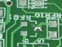
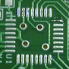
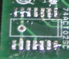 Step 5 Suck the solder off the pads
ready for the new part. Step 5 Suck the solder off the pads
ready for the new part.
|
|
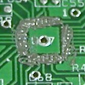
BGA, MLF / MLA de-soldering :
|
|
Cover the PCB in tin foil except for the BGA, MLF / MLA part and the area around it. Heat the part / PCB
8cm ( 3") away with a heat gun. Try heating both the top and bottom side of the PCB. Keep side pressure on
the part with fine point needle-node pliers so it will slide off when the solder melts.
|
|
Author : DrWho
March 2003