NOTE
This project has been superseeded by DTMF Decoder 2
Disclaimer
This device and all information contained on this website is for educational purposes only. This device must be used in conjunction with any and
all local, provincial and federal laws. It is up to the end user to comply with all legal guidelines, thus we are not and will not be held
responsible for any misuse of this product or any damages that it may cause.
Description
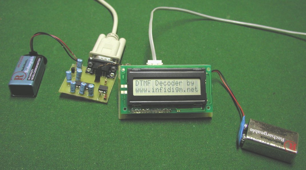
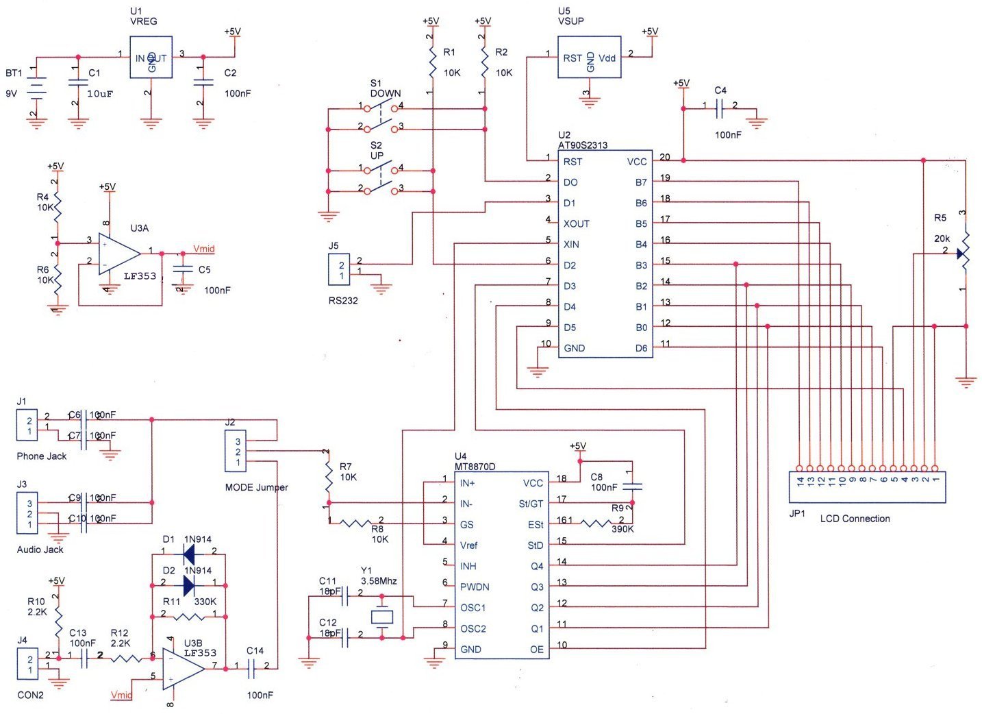
The DTMF decoder is a useful tool used for decoding DTMF (Dual Tone Multi frequency) generated by telephones. The decoded digits are viewed on a
16x2 LCD screen. A interface can be connected between the DTMF decoder and a Serial port to view the digits in Hyperterminal on a computer. The
decoder stores the last 255 received digits in EEPROM. The contents of EEPROM can be viewed on the LCD screen via two scroll buttons. Total power
consumption is 17mA. The DTMF decoder has three inputs. A RJ11 jack for connecting to the phone line. A 1/8" audio jack for connecting to a
scanner, tape recorder or other audio output device. A microphone with a 6-12" range.
Assembly
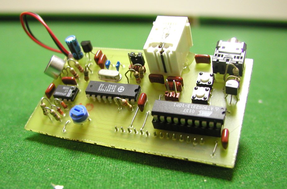 The DTMF Decoder and Serial interface Board can be
assembly by anyone with general electronic knowledge and soldering skills.
The DTMF Decoder and Serial interface Board can be
assembly by anyone with general electronic knowledge and soldering skills.
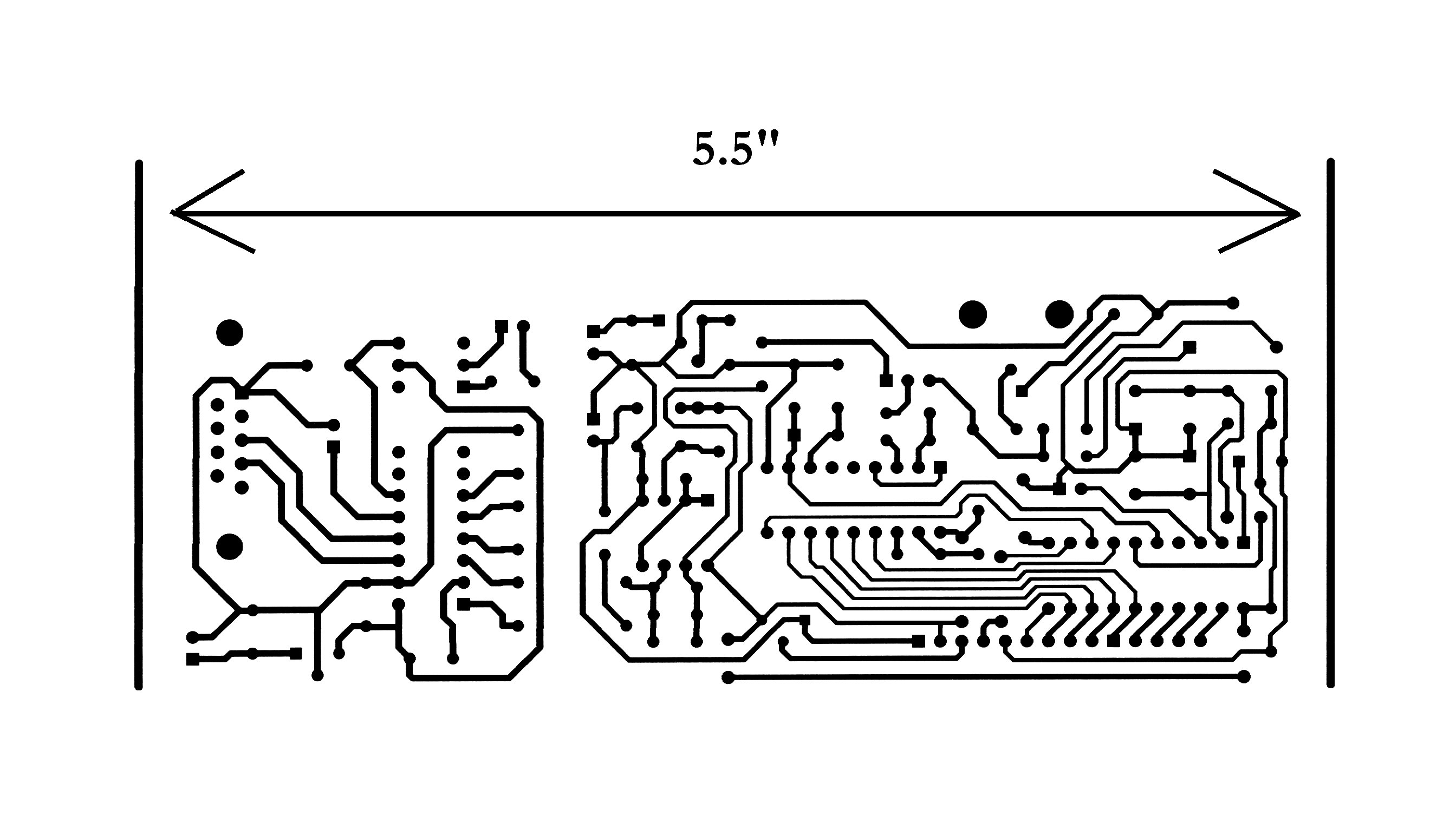
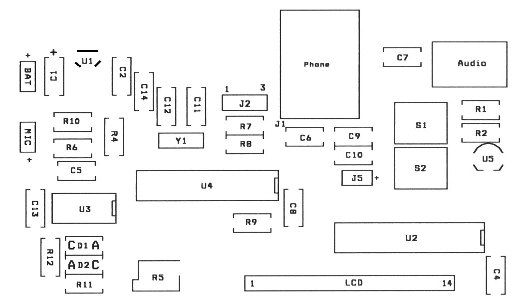
A PCB layout is provided if one wishes to construct their own PCB. Simply print the file at 1:1 onto an overhead transparency. (Get the correct sheet for your type of printer) I used a kit by MG Chemicals (E-Sonic Search for 416-K) to produce my PCB. The provided PCB layout's smallest traces are 15 thou wide. Drill the holes for the headers at 40 thou. Drill the holes for the 20K POT, the buttons, and the audio jack at 35 thou. Drill the rest of the holes at 30 thou. Drill bits can be found a most hobby stores.
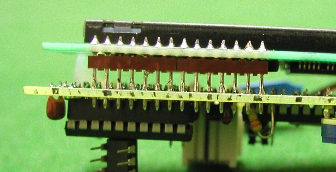
Review the schematic and parts placement diagram before beginning assembly for proper orientation of diodes, ICs and capacitors. Begin by installing the seven jumper wires. Next solder in all the resistors and capacitors. Then solder in the buttons, the phone and audio jack, the two headers, the 20K POT and the crystal. Solder in the 20 pin socket, ICs, diodes and Mic. Be sure that the Mic's ground (tab that has traces connected to Mic's case) goes to the decoder's ground. Finally install the two, seven pin headers into the LCD (short side towards LCD). Solder the longer side of the headers into the DTMF decoder PCB. Attach the LCD and decoder together with hot glue or other means. At this point, test the decoder for +5V between pins 10 and 20 on the 20 pin socket.
Programming the Atmel AVR AT90S2313 is the final step. A programmer can be bought from Digikey (Search for STK500) . Here is a link to a simple AVR programmer. Simply Write dtmf.hex to the 2313 and then install the micro into the DTMF decoder. Power the decoder up, adjust the contrast, and the message "DTMF Decoder ......" should appear on the screen.
Usage
To use the DTMF decoder, simply connect it to a 9V battery and the phone line. The DTMF decoder will accept ISOLATED DC voltages from 7 to 20 V.
Upon power up the Message "DTMF decoder by www.infidigm.net" appears on the LCD screen. The message will remain there until a DTMF digit is
received or a scroll button is pressed. If a DTMF digit is received while scrolling through EEPROM, the LCD screen is restored and the digit is
appended to the end of the line. The LCD will auto scroll at the end of each line. Their are two scroll buttons, UP and DOWN. They will shift the
last 255 digits through the LCD screen 16 at a time. UP will move towards the oldest received digit while DOWN will move towards the most
recently received digit. A jumper is used to select between the phone line / audio jack input and the microphone. Remember to set the 20K pot for
LCD CONTRAST adjustment.
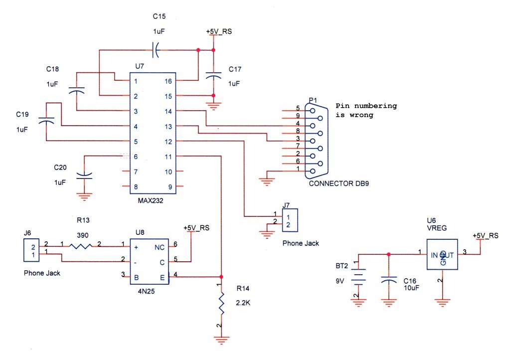
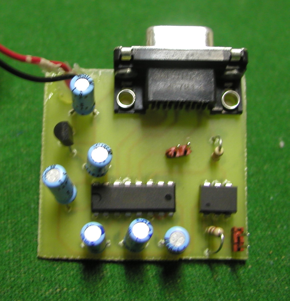 To connect the DTMF Decoder to the computer a Serial
interface board is used. The interface consists of a MAX232 and a 4N25 Opto-isolator. The interface is TX only. This means that the information
can only be sent from the DTMF decoder to the computer. Connect a 9V battery to the interface board. A SEPARATE power source must be used from
the DTMF decoder because the phone line must be electrically isolated from the computer's ground. (Purpose of the 4N25) Connect a DB9 pin serial
cable to the interface board and the computer. Connect a two-wire jumper cable from the DTMF Decoder to the interface board. It may be necessary
to rotate the jumper wire 180 degrees for proper polarity. Open Hyperterminal and setup a new connection for the appropriate COMM port. Set BAUD
to 9600 8-N-1.
To connect the DTMF Decoder to the computer a Serial
interface board is used. The interface consists of a MAX232 and a 4N25 Opto-isolator. The interface is TX only. This means that the information
can only be sent from the DTMF decoder to the computer. Connect a 9V battery to the interface board. A SEPARATE power source must be used from
the DTMF decoder because the phone line must be electrically isolated from the computer's ground. (Purpose of the 4N25) Connect a DB9 pin serial
cable to the interface board and the computer. Connect a two-wire jumper cable from the DTMF Decoder to the interface board. It may be necessary
to rotate the jumper wire 180 degrees for proper polarity. Open Hyperterminal and setup a new connection for the appropriate COMM port. Set BAUD
to 9600 8-N-1.
Upon power up the DTMF decoder will send the message "DTMF Decoder by www.infidigm.net" to Hyperterminal along with the last 255 received digits from EEPROM. Every time a DTMF is received, the decoder will send the digit to Hyperterminal.
Parts List
The list includes parts for the DTMF Decoder and the Serial Interface Board.
Bolded Components are for the Serial Interface Board
| Quantity | Value | Description | Digikey Part No. | Component |
| 2 | 78L05 | +5V Regulator | 296-1365-1-ND | U1,U6 |
| 1 | MCP120 | MCP120-450DI/TO-ND | U5 | |
| 1 | AT90S2313 | Microprocessor | AT90S2313-10PI-ND | U2 |
| 1 | MT8870DE | DTMF Decoder | E-SONIC | U4 |
| 1 | LF353 | Opamp | LF353N-ND | U3 |
| 1 | MAX232N | Max232 | 296-1402-5-ND | U7 |
| 1 | 4N25 | Opto-isolator | 160-1300-5-ND | U8 |
| 2 | 1N4148 | Signal Diode | 1N4148MSCT-ND | D1,D2 |
| 10 | 0.1 uF | P4525-ND | C2,4,5,6,7,8,9,10,13,14 | |
| 2 | 18pF | P4840-ND | C11,C12 | |
| 2 | 10uF | Dielectric | P10316-ND | C1,C16 |
| 5 | 1uF | Dielectric | P10312-ND | C15,17,18,19,20 |
| 6 | 10K | 1/4 Watt | 10KQBK-ND | R1,2,4,6,7,8 |
| 2 | 390K | 1/4 Watt | 390KQBK-ND | R9,R11 |
| 3 | 2.2K | 1/4 Watt | 2.2KQBK-ND | R10,R12,R14 |
| 1 | 390 | 1/4 Watt | 390QBK-ND | R13 |
| 1 | 20K POT | Vertical POT | 36G24-ND | R5 |
| 1 | 16x2 | LCD | 73-1025-N | LCD |
| 1 | RJ 11 Jack | CCM9000-ND | Phone | |
| 1 | 1/8 Audio Jack | CP-3543N-ND | Audio | |
| 2 | 9V Connector | BS6I-HD-ND | Batt,Batt | |
| 1 | 20-pin Socket | A9420-ND | ||
| 2 | Push Buttons | P8006S-ND | S1,S2 | |
| 3 | 0.1" | 7-pin Header strip | WM4005-ND | |
| 1 | Jumper | A26228-ND | ||
| 1 | 3.579545 Mhz | 3.58 Mhz Crystal | 300-6001-ND | Y1 |
| 1 | Female | DB9 Connector | A2100-ND | DB9 |
| 1 | Microphone | P9897-ND | MIC |
Files
DTMF decoder Schematic
DTMF decoder PCB Layout
DTMF decoder Parts Placemant
Assembly Code for AT90S2313
Hex file for AT90S2313
Serial Interface Schematic
Serial Interface PCB Layout
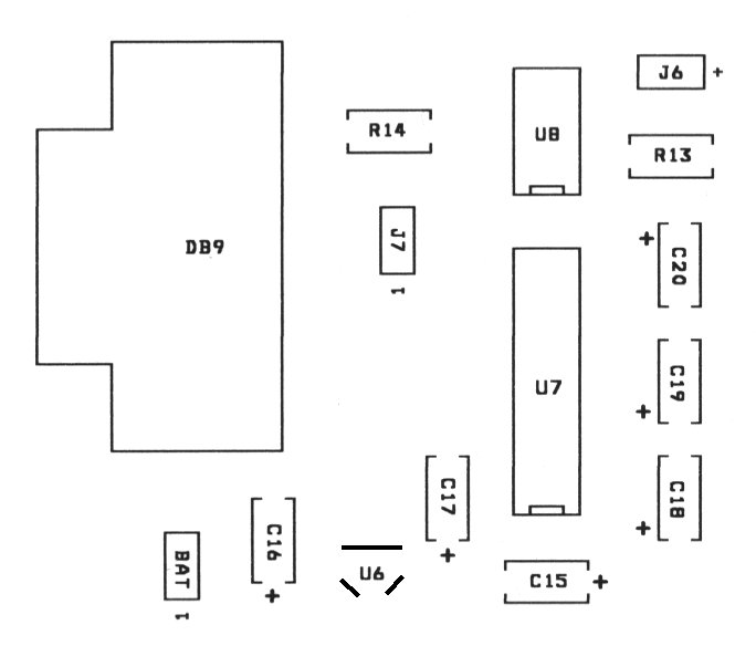
Serial Interface Parts Placemant
AT90S2313 Data Sheet (Microprocessor)
MT8870DE Data Sheet (DTMF Decoder)
LCD Data Sheet