The RS-232 to Microplex (MPX) Interface allows the PC to control Microplex devices. The interface converts a serial data stream from the PC into the microplex protocol. The interface gets power through the XLR cable from other MPX devices (Dimmer Box). The interface can be programmed through the PC to control between 6 - 96 channels. The interface is also electrically isolated from the PC serial port. The total cost of this project is around $65 CAN.
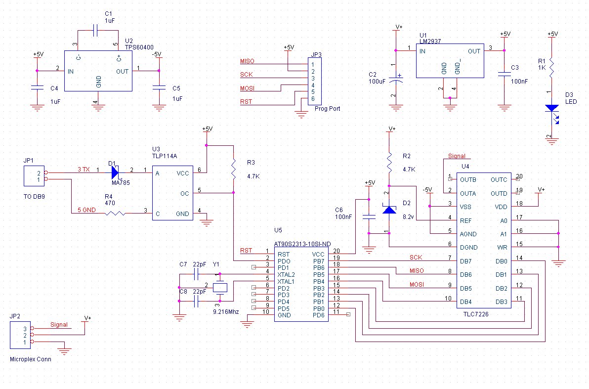
Opto-isolator U3, D1, R3 and R4 form a line receiver for the RS-232 connection. The serial port's (PC) ground is not connected to the interface's ground by use of U3. This provides electrical isolation. Power supply for the interface consists of a +/- 5v supply. U1, C2 and C3 form a +5v linear supply. U2, C1, C4 and C5 are used to form an inverting Charge pump circuit which converts the +5v into -5v. R2 and D2 form a 8.2v reference. U4 is a voltage output Digital-to-Analog converter and is used to form the analog MPX signal. The DAC has an output range of -5v to +8v sufficient for MPX signaling. This is accomplished by connecting AGND to -5v and REF to the 8.2v reference. VDD on the DAC is required to be 4 volts higher than the REF and thus it is connected to the +12v on the XLR cable. The DAC's digital inputs are driven by the 8 bit port on microcontroller U5. U5 is clocked by a 9.216 Mhz crystal. This frequency was chosen for UART baud rate compatibility. Pin 2 of U5 is the UART Rx pin and is connected to U3's open collector output. C6 is used as a bypass capacitor across U5's supply pins to keep +5v supply clean.
A PCB Layout is provided. Simply print the file onto an overhead transparency. (Get the correct sheet for your type of printer) I used a kit by MG Chemicals (Active or E-Sonic Search for 416-K) to produce my PCB. The provided PCB layout's smallest traces are 10 thou wide. Drill all holes at 35 thou. Small drill bits can be found a most hobby stores. Holes are needed for the serial wires (2) and for the MPX XLR connector (3). Drill two 3/16" mounting holes at the markers on each side of the board.
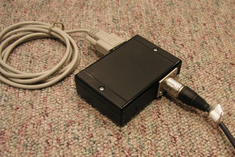
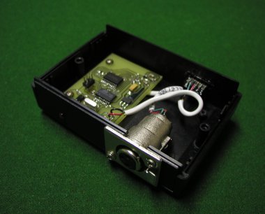
The Enclosure must be modified to hold the XLR connector and the DB9 connector. Both connectors are mounted in the side slots of the box. For the DB9 a hole is cut and shaped. For the XLR the side slot must be cut in two and shaped round to fit around the XLR. Glue the DB9 into place and screw the XLR into place.
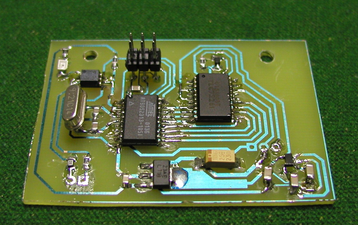
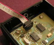
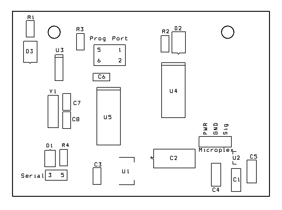
Once the PCB is complete and the enclosure is ready, population is next. Please review the Parts Placement diagram before beginning and throughout assembly. Begin by soldering U2 and U3 because they are the hardest parts to solder. Please see Infidigm's soldering guide for instructions on soldering these small packages. The crystal and programming port are soldered on the top side of the board as the pictures indicate. Solder on all resistors and capacitor being mindful of Tantalum C2's polarity (Bar = Pos+). U1, U4, U5, D1, and D2 are next. Solder on the wires for the XLR and serial connectors. Bring the PCB close to the box and solder the other ends of the wires to the connectors. Refer to the parent article to determine where to connect each wire on the XLR connector. Screw the PCB to the box at this point. The final step is to place the LED in the box and then solder it to the PCB.
Feel free to email me with questions / problems at "drwho at infidigm dot net". I may not respond to all questions.
Programming the microcontroller is the next step. The micro is a AVR AT90S2313 made by ATMEL. An AVR ISP (Incircuit Serial Programmer) compatible programmer is required. Here is a list of programmers.
Only read this section if you wish to modify the
program!
The program is written in C. It consists of one C file and was written to be complied under the
free AVR-GCC C compiler (WinAVR 3.4.3 February 14,
2005). Read the beginners guide to learn how to install GCC. Once you have GCC
working, download the Project Files for Programmers NotePad. and unzip them
to a directory of your choosing. Run Programmers NotePad ( /WinAVR/pn/pn.exe). In PN go
"File-->Open Project(s)" and select "mpx.pnproj" in the directory where you unzipped "mpxfirmw.zip".
Open "mpx.c by double clicking on it. Click "Tools-->Make All" to test the Compiler.
The program is well documented and self explanatory.
| Quantity | Value | Description | Digikey Part No. | Component |
| 1 | AT90S2313 | Microprocessor | AT90S2313-10SI-ND | U5 |
| 1 | TLC7226 | Voltage DAC | 296-3019-5-ND | U4 |
| 1 | TLP112A | Opto-coupler | TLP112A-ND | U3 |
| 1 | TPS60400 | Inverting Charge Pump | 296-12013-1-ND | U2 |
| 1 | LM2937 | Voltage Regulator | LM2937IMP-5.0CT-ND | U1 |
| 1 | BZT52C8V2S-7 | 8.2 v zener | BZT52C8V2SDICT-ND | D2 |
| 1 | MA785 | Schottky diode | MA785CT-ND | D1 |
| 1 | LN89RCPP | Red LED | P371-ND | D3 |
| 1 | 100uF | Tantalum Cap | 399-1777-1-ND | C2 |
| 2 | 0.1uF | SMD Cap | PCC1828CT-ND | C3,C6 |
| 2 | 1uF | SMD Ceramic | PCC1893CT-ND | C1,C4,C5 |
| 3 | 22pF | SMD Cap | PCC220CNCT-ND | C7,C8 |
| 1 | 470 | SMD Res | P470ACT-ND | R4 |
| 1 | 1K | SMD Res | P1.0KACT-ND | R1 |
| 2 | 4.7K | SMD Res | P4.7KACT-ND | R2,R3 |
| 1 | 9.216 Mhz | Crystal | 300-6019-ND | Y1 |
| 1 | 6 pin | 0.1" header 2x3 | WM6636-ND | Prog Port |
| 1 | 9 pin | DB-9 Connector | A2001-ND | |
| 1 | 3 pin | XLR Female Connector | 274-013A | Radio Shack |
| 1 | 4.5x3x1.3" | Plastic Enclosure Box | 75054-510-000 | Active |
| 1 | 4x6" Pre-syn. PCB | MG Chemicals | 687 | Active |
Microplex interface Schematic
PCB Layout (Mirror
image)
Parts Placement diagram
All Program Project Files.
C Source Code
Hex file for AT90S2313
AT90S2313
Data Sheet (Microprocessor)
TLP7226 (8
bit DAC)
TPS60400
(Inverting Charge Pump)
TLP114A (Optocoupler)
Connect the interface to the PC with a 9-pin straight through serial cable; one end male, the other end female. The UART is setup for 38400 BAUD which allows data to enter the interface faster that it can escape through the MPX protocol. Their are four types of data bytes that can be sent to the interface; Commands, Addresses, Channel value levels and Channel length. Their are two commands which are 0xAA and 0xA7. 0xAA is used to tell the interface that the next byte will be a channel address and the byte after that will be level value for that channel. 0xA7 is used to program the channel length into the interface where the next byte is the number of channels of the MPX protocol. Channel length can be between 6 and 96 channels. Valid address are 6 to the programmed channel length. Valid channel levels ranges from 0 to 159. The light is off at 0 and all the way on at 159.
To change a light level send 0xAA, then the address of the light you want to change (6-96), and then the level (0-159). After ever data byte sent the interface automatically increments to the next channel address. This makes it possible to "mass program" sequential addresses with only telling the interface the address of the first.